AdaOne User Camp 2026

The AdaOne User Camp 2026 was a week-long exploration of AdaOne, bringing together users from around the world to dive deeper into advanced workflows and practical applications. Browse through the sessions below to find packed projects available for download and a quick slideshow summarizing what each session covered.
This session demonstrates the cell setup and post-processing workflow in AdaOne. First, a digital twin of the manufacturing cell is configured, including the robot, tools, and relevant equipment. The complete toolpath can then be simulated to check for collisions, reachability, and singularities before generating the final robot code, allowing the program to be fully validated prior to running it on the physical cell.
This session demonstrates how the post processor in AdaOne can be customized to generate programs tailored to a specific manufacturing setup. Custom commands and variables can be defined and combined with mathematical expressions to control how toolpath and process data are translated into the output program. Controller-specific modifications can also be implemented, allowing the generated code to be adapted to the requirements of different machines, controllers, and manufacturing processes.
This session reviews the fundamentals of path planning, starting with the benefits of additive manufacturing and why having the right strategy is essential for effective toolpath generation. A robot simply executes the program it is given, meaning the quality of the final part depends heavily on how that program and toolpath are created. By defining a clear path planning strategy based on the desired result, the manufacturing process can be better controlled and optimized to achieve the intended final product.
This session introduces the fundamentals of path planning in AdaOne, starting from either STL or STEP files depending on the application. Based on the desired result, different aspects of the toolpath can be adjusted, including layer time, deposition parameters, layer height and width, and overall path strategy. These parameters can then be refined and optimized to achieve the desired manufacturing result while improving the overall toolpath performance.
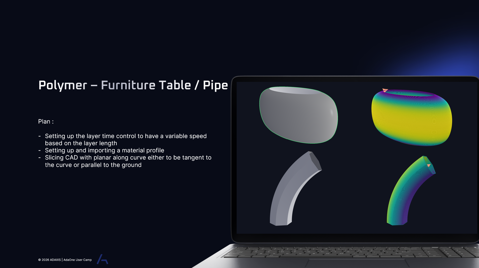
For polymer furniture applications, layer time control can be used to manage cooling and bonding across varying layer lengths, while different material profiles allow extrusion parameters to be adapted for different calibrations. A planar-along-curve slicing strategy can also be used to generate toolpaths with varying layer heights, providing greater control when printing more complex geometries.
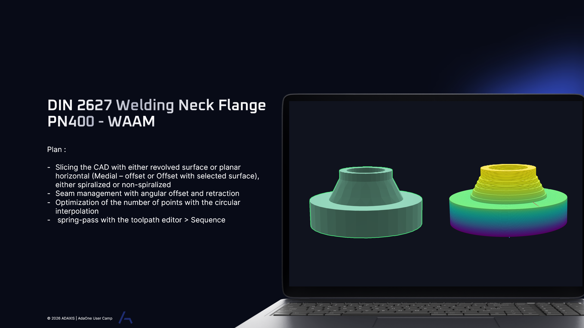
For welding a neck flange, slicing can be performed using either revolved or horizontal planar strategies depending on the geometry and deposition requirements. Seam management using angular offsets and retraction helps minimize material buildup, while multiple toolpath strategies can be sequenced together to create a continuous welding process.
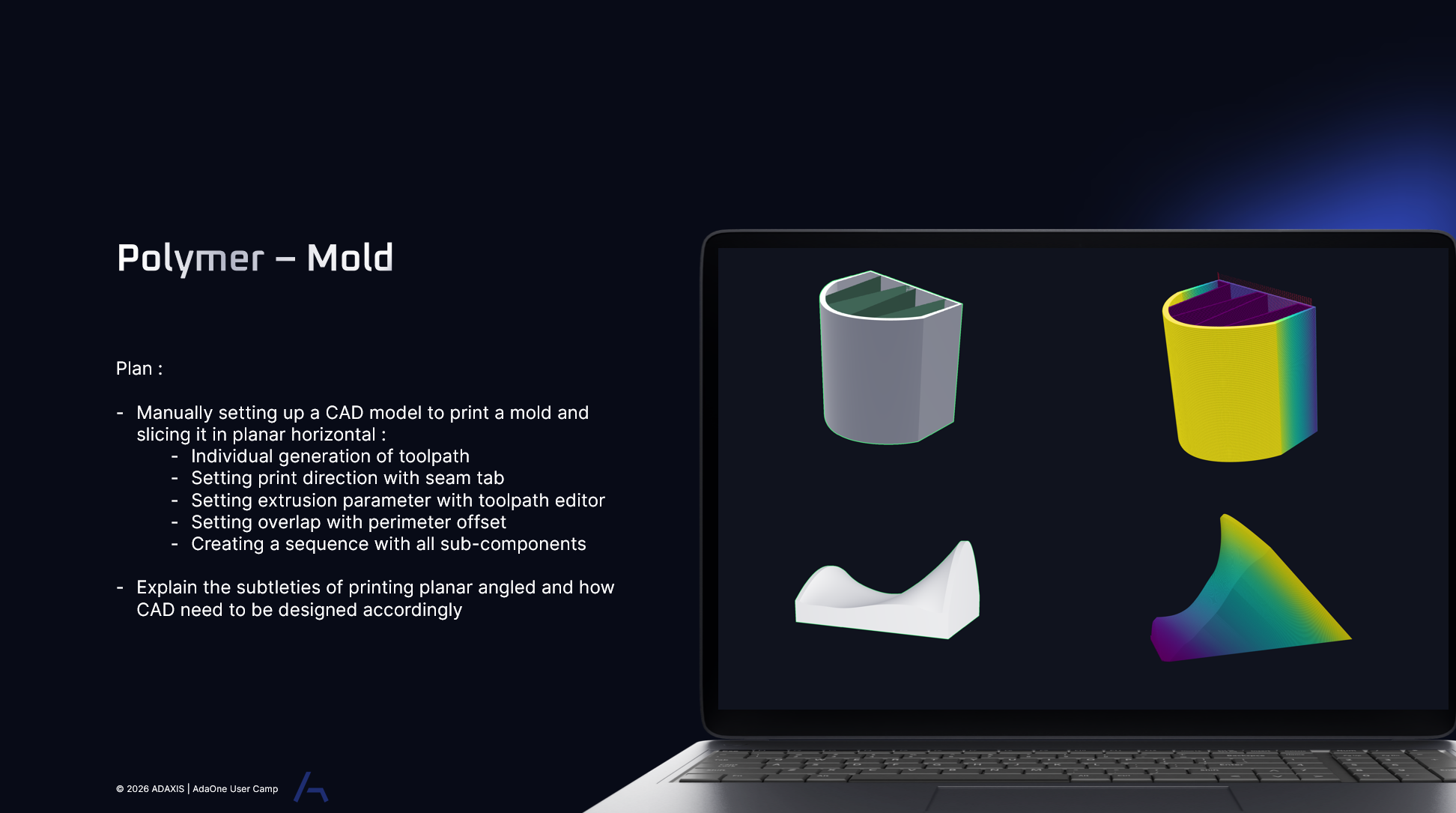
For polymer mold printing, the print direction and extrusion parameters can be defined to maintain full control over material deposition throughout the process. Overlap parameters can be adjusted to ensure consistent bonding between toolpaths, while the different printing strategies are combined into a single coordinated sequence.
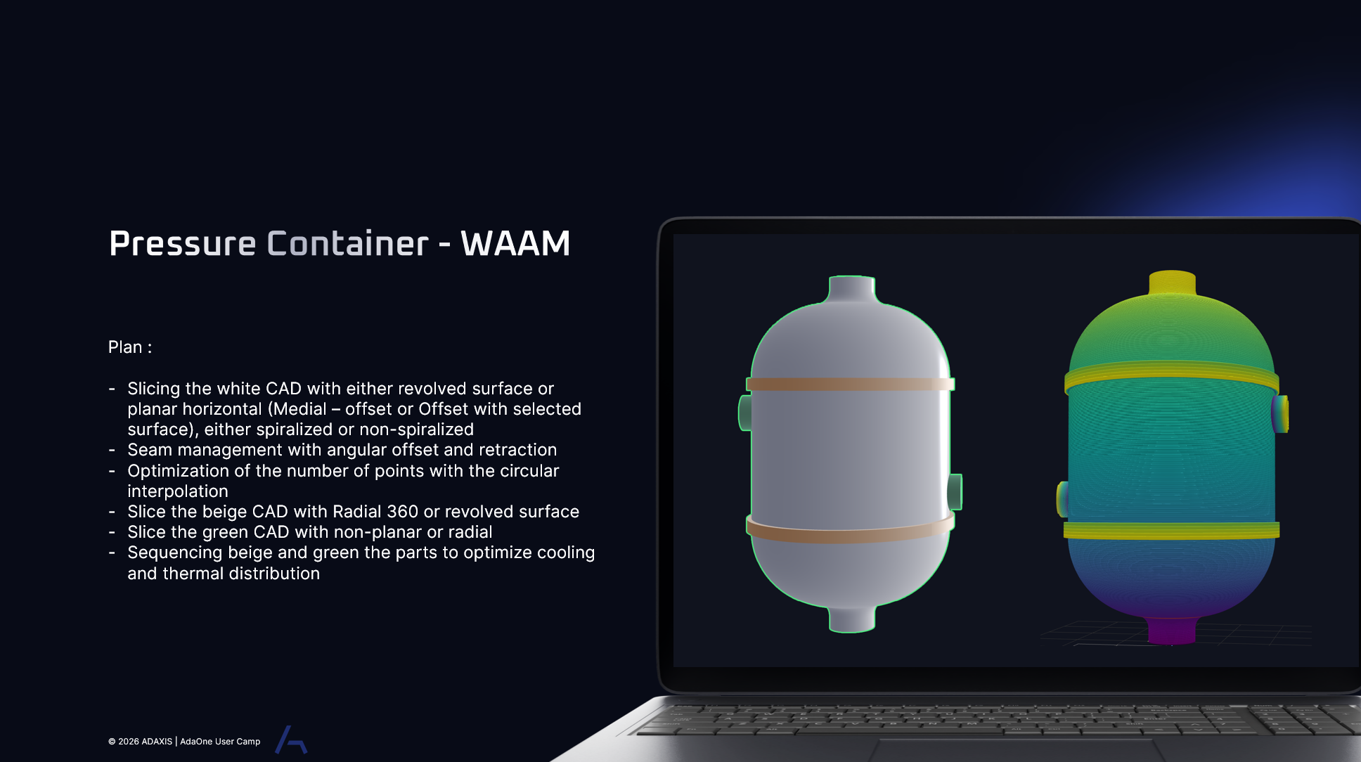
Path planning for metal applications, such as a pressure container, can use a revolved surface to generate slicing strategies that follow the geometry of the part. The toolpath can then be optimized by reducing the number of points through circular interpolation and sequencing multiple slicing strategies into a single continuous manufacturing process.
This session introduces the fundamentals of subtractive path planning, from configuring a digital twin for milling to setting up the spindle, feeds, and speeds. Using the spindle library, machining parameters can be defined and adapted to the specific manufacturing setup. Different types of part imports also enable different milling strategies, ranging from planar clearing to more advanced multi-axis finishing, allowing the toolpath to be selected and optimized based on the geometry and desired final result.
This session demonstrates different approaches for aligning a digital part with its physical counterpart using either a probed workframe or a probed part. For simpler applications, alignment can be achieved using a reduced set of parameters to snap the two parts together. For more complex geometries, the Part Alignment Workflow provides a more extensive process using additional probing points on the physical part to accurately determine its position and orientation.
This session demonstrates how the Toolpath Editor can be used to modify toolpath characteristics after the initial toolpath has been generated. Beads, layers, or individual target points can be selected and filtered based on specific criteria, such as toolpath type, bead overhang, or other toolpath characteristics. Parameters such as deposition, speed, and other process settings can then be adjusted either across the overall toolpath or within highly specific areas, providing greater control over the final manufacturing program.
This session demonstrates how toolpath analytics and thermal simulation can provide meaningful insights into the manufacturing process before production begins. Real-time thermal simulations can be used to evaluate and better understand thermal behavior for both metal and polymer additive manufacturing. Additional toolpath data, including total manufacturing time and material usage, can also be accessed to better evaluate and optimize the overall process.
This session explains how toolpath orientation and rotation can be visualized and diagnosed across different areas of AdaOne, including the Toolpath Editor. Orientation is defined as a vector that controls how the process head is aligned along the toolpath, while rotation is a single scalar value defined relative to that orientation. Understanding the relationship between the two makes it easier to identify orientation issues and precisely control the behavior of the process head throughout the toolpath.
This session introduces the basics of the Infill Designer and how infill can be adapted throughout different areas of a part. Infill can be applied to specific layers while adjusting parameters such as density and infill type based on the requirements of the geometry. This allows additional rigidity to be introduced only where it is needed, while reducing material usage and manufacturing time in less critical areas.
This session explores an intermediate polymer workflow using the Infill Designer to create targeted support based on the geometry of the part. Areas with overhangs can be identified and reinforced by adding infill where additional support is required. Different infill types and parameters can then be applied throughout the part, allowing the level of support to vary based on the needs of each region while optimizing material usage and print time.
This session explores an advanced polymer workflow using imported surfaces as modifiers to create custom infill strategies. Surfaces can be brought into AdaOne and used to define specific regions within the part, allowing the infill behavior to change based on their position and geometry. This provides greater control over the internal structure of the part, enabling customized infill based on specific structural, support, or manufacturing requirements.
This session demonstrates a beginner-friendly workflow between Grasshopper and AdaOne for furniture and industrial design applications. A simple parametric geometry is first created in Grasshopper, then transferred to AdaOne for slicing and pattern generation. Using the Grasshopper Bridge, design changes such as dimensions, proportions, or surface variations can be synchronized in real time, automatically updating the toolpath without the need to re-import or re-slice the part.
This session explores an intermediate workflow between Grasshopper and AdaOne, combining parametric pattern generation with more advanced slicing strategies. Custom patterns and geometries are created and controlled in Grasshopper, then transferred to AdaOne where more complex slicing and toolpath strategies can be applied. Using the Grasshopper Bridge, design changes can be synchronized directly with the manufacturing workflow, allowing both the geometry and toolpath strategy to be refined as the design evolves.
This session explores a parametric workflow for metal additive manufacturing using components such as rocket nozzles and other geometries that can be adapted based on design requirements. Key dimensions and geometric features are controlled parametrically in Grasshopper, then transferred to AdaOne for slicing and toolpath generation. Using the Grasshopper Bridge, design iterations can be quickly synchronized with the manufacturing workflow, making it easier to evaluate and generate toolpaths for different part variations.
This session explores a parametric workflow for large-scale polymer additive manufacturing, focusing on architectural elements designed to be manufactured and assembled from multiple parts. Grasshopper is used to parametrically divide and modify larger geometries while considering how individual sections will connect and come together during assembly. Using the Grasshopper Bridge, these components can be transferred to AdaOne for slicing and toolpath generation, connecting design, fabrication, and assembly within a flexible workflow.
This session explores a parametric workflow for metal additive manufacturing, focusing on larger components such as propeller blades that can be divided into multiple sections for manufacturing and assembly. Grasshopper is used to parametrically define and modify the individual sections while considering their connections and final assembly. Using the Grasshopper Bridge, each component can then be transferred to AdaOne for slicing and toolpath generation, creating a flexible workflow from the overall design to the manufacturing of individual parts.
Smart Sequencing allows you to combine toolpaths across multiple processes, including printing, scanning, and thermal scanning, within a single coordinated sequence. With a multi-tool setup defined in the digital twin, you can customize when thermal scans are captured, such as per bead or per layer, and sequence scan toolpaths in parallel by applying the same scan strategy to each layer or grouping toolpaths to apply different scanning strategies.
Smart Sequencing allows you to combine toolpaths across multiple processes, including printing, scanning, and thermal scanning, within a single coordinated sequence. With a multi-tool setup defined in the digital twin, you can customize when thermal scans are captured, such as per bead or per layer, and sequence scan toolpaths in parallel by applying the same scan strategy to each layer or grouping toolpaths to apply different scanning strategies.
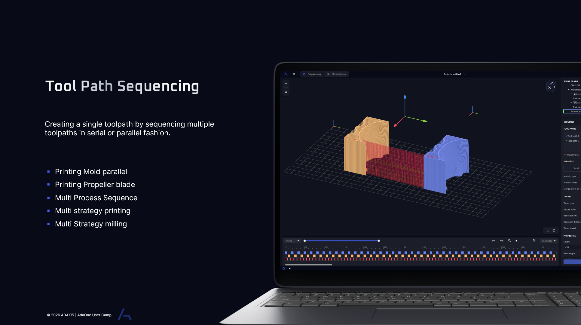
Toolpath sequencing allows you to combine multiple toolpaths into a single coordinated sequence, arranging them to run either in serial or in parallel. This enables more complex manufacturing workflows, such as printing multiple molds simultaneously, coordinating the printing of individual propeller blades, or combining different strategies and processes such as printing and milling within the same sequence.